
The PLC Tools SIM-ALP2 Analog Simulator 4-20mA and 0-10VDC User Manual can simulate a 4-20mA 2 wire current loop, a 4-20mA 4 wire current source, and a 0-10VDC voltage source.
For the most up to date demonstration of features, watch the How to Simulate a 4-20mA or 0-10VDC Analog Signal - PLC Tools SIM-ALP2. Only the basic steps to simulating an analog signal are shown below.
Specifications:
Current Output
0-22mA Two-Wire Device
0-22mA Current Source
Output Range 0mA to 22mA
Fixed Steps 1mA or 0.1mA increments
Output Accuracy ±1% of full scale at 25°C
Load Range 0-500 Ohm
Voltage Output
+/-10 V Voltage Source
Output Range -10V to 10V
Fixed Steps 1V or 0.1V increments
Output Accuracy ±1% of full scale at 25°C
Minimum Load 20kOhm
Protection
Reverse Polarity
Electronic Fuse
Open Wire (Current)
Excessive Loop Voltage
Output Short (Voltage)
Power Supply
Internal Power Battery 2xAA
Ni-MH or Alkaline
2-Wire Current 12-30V DC External Power
Temperature range
0-50°C
DISCLAIMER - This device is intended to provide general assistance with current loop and analog input debugging, testing, and application development. It should not be permanently used in live production systems.
Accordingly, production system must be tested and commissioned with calibrated instruments to ensure safe and reliable operation.
IN NO EVENT SHALL THE DEVICE MANUFACTURER BE LIABLE FOR ANY DAMAGES OF ANY KIND INCLUDING DIRECT, INDIRECT, INCIDENTAL, CONSEQUENTIAL, LOSS OF PROFIT, OR DAMAGE.
The examples and diagrams in this manual are included for illustrative purposes only. Because of the many variables and requirements associated with any particular installation, the device manufacturer cannot assume responsibility or liability for actual use based on the examples and diagrams.
Before making any decision or taking any action that might affect your equipment, you should consult a qualified professional adviser.
Current 2-Wire
Output Range 0mA to 22mA
Fixed Steps of 0.1mA or 1mA increments
Output Accuracy ±1% of full scale
Load Range 0-500 Ohm
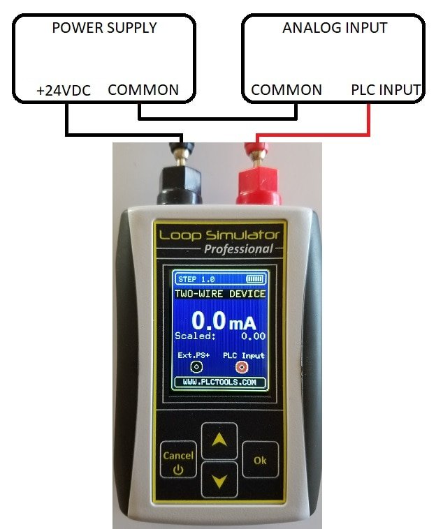
To enter Current 2 Wire, select Current 2 Wire from the main menu.
Near the bottom of the screen, you will see the terminal connection diagram which says to connect the + of the external power supply to the black terminal and the input to the red terminal. Don't forget to connect the common of your external power supply to the common of your PLC input.
Pressing the UP and DOWN buttons will increment through 4-20mA values (0-22mA full scale) in either 0.1 or 1.0 mA increments depending on the resolution selected.
Current Source
Output Range 0mA to 22mA
Fixed Steps of 0.1mA or 1mA increments
Output Accuracy ±1% of full scale
Load Range 0-500 Ohm
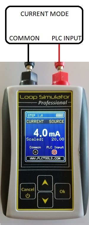
To enter Current Source, select Current Source from the main menu.
Near the bottom of the screen, you will see the terminal connection diagram which says to connect the Common of the analog input to the black terminal and the input to the red terminal.
Pressing the UP and DOWN buttons will increment through 4-20mA values (0-22mA full scale) in either 0.1 or 1.0 mA increments depending on the resolution selected.
Voltage Source

Output Range -10V to 10V
Fixed Steps 0f 0.1V or 1V increments
Output Accuracy ±1% of full scale
Minimum Load 20kOhm
To enter Voltage Source, select Voltage Source from the main menu.
Near the bottom of the screen, you will see the terminal connection diagram which says to connect the Common of the analog input to the black terminal and the input to the red terminal.
Pressing the UP and DOWN buttons will increment through 0-10VDC values (-10 to +10VDCfull scale) in either 0.1 or 1.0 mA increments depending on the resolution selected.